
Inside the Mud Tank: How It Powers Drilling Fluid Circulation

Every drilling rig depends on a continuous loop of drilling fluid moving from surface to bottom hole and back again. At the center of that loop sits the mud tank, a piece of equipment that often goes unnoticed but quietly makes the entire operation possible. From storing thousands of cubic metres of fluid to separating out damaging solids and stabilising pressure across the system, the mud tank carries responsibilities that directly affect drilling safety and efficiency. KOSUN manufactures high-performance mud tanks built for reliable service in every drilling environment.
What Goes Into a Mud Tank?

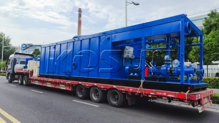
A modern mud tank is more than a steel container. It combines a tank body, mixing mechanism, level monitoring system, flow pipelines, and interconnecting fittings into one integrated unit.

The tank body itself is welded from heavy steel plate, engineered to withstand continuous service. Inside, the mixing mechanism keeps solids from settling to the bottom. The level monitoring system tracks fluid height in real time, protecting against overflow on one end and pump starvation on the other. Together, these elements create a system that performs reliably around the clock.

How the Mud Tank Functions

Fluid Storage: The tank holds a stable reserve of drilling fluid, allowing operations to continue without interruption.

Fluid Circulation: Pumps pull mud from the tank and send it downhole; the returning stream carries cuttings back to complete the cycle.

Solids Removal: Vibrating screens, desanders, and desilters installed on the tank strip out cuttings and finer particles, raising mud purity.

Fluid Conditioning: Operators introduce chemical treatment agents to adjust viscosity, density, and other properties according to formation requirements.

Level Management: Sensors monitor mud height and control pump activity to keep levels steady.

Four Critical Roles of the Mud Tank
  1. Storage Capacity That Keeps Drilling Moving

The mud tank’s most fundamental job is holding enough drilling fluid to sustain continuous operations. In ultra-deep wells, that can mean storage capacity measured in thousands of cubic metres.

Beyond routine supply, the tank also acts as an emergency reserve. When a well surge or leak occurs, stored fluid can be deployed immediately to bring downhole conditions under control.

  1. Purification That Protects Equipment

As drilling fluid circulates, it collects rock cuttings. Left in the system, those solids cause equipment damage. Working alongside vibrating screens, desanders, and desilters, the mud tank helps separate solids effectively, extending both fluid performance and equipment service life.

Harmful gases present a second purification challenge. Hydrogen sulphide (H₂S) and methane (CH₄) can dissolve into the fluid, creating safety hazards. Mud tanks address this with gas discharge devices such as breathing valves. More advanced designs incorporate degassers for an added layer of protection.

  1. Blending That Matches Formation Conditions

Drilling fluid properties must be adjusted as formations change. Adding barite increases density, for example, while chemical treatments modify viscosity. Through accurate mixing within the mud tank, operators ensure the fluid meets the demands of each drilling stage.

  1. Stability That Holds the System Together

The mud tank buffers the pressure and flow fluctuations that naturally occur during drilling. When pump output climbs, the tank absorbs the excess fluid; when output drops, it releases stored fluid to fill the gap. This buffering protects equipment and keeps circulation steady.

The tank also serves as the connecting hub between vibrating screens, desanders, desilters, and mud pumps. By linking these components, it maintains orderly flow and keeps every piece of equipment working in harmony.

Conclusion

Mud tanks are far more than storage vessels, they are the backbone of the drilling fluid circulation system. By providing reliable storage, removing solids and harmful gases, enabling precise blending, and stabilising system pressure, they contribute directly to safe and efficient drilling. KOSUN is committed to delivering high-performance mud tanks and expert support to help customers achieve their operational goals.
Drilling Fluid Vibrating Screen: Three Factors That Shape Performance

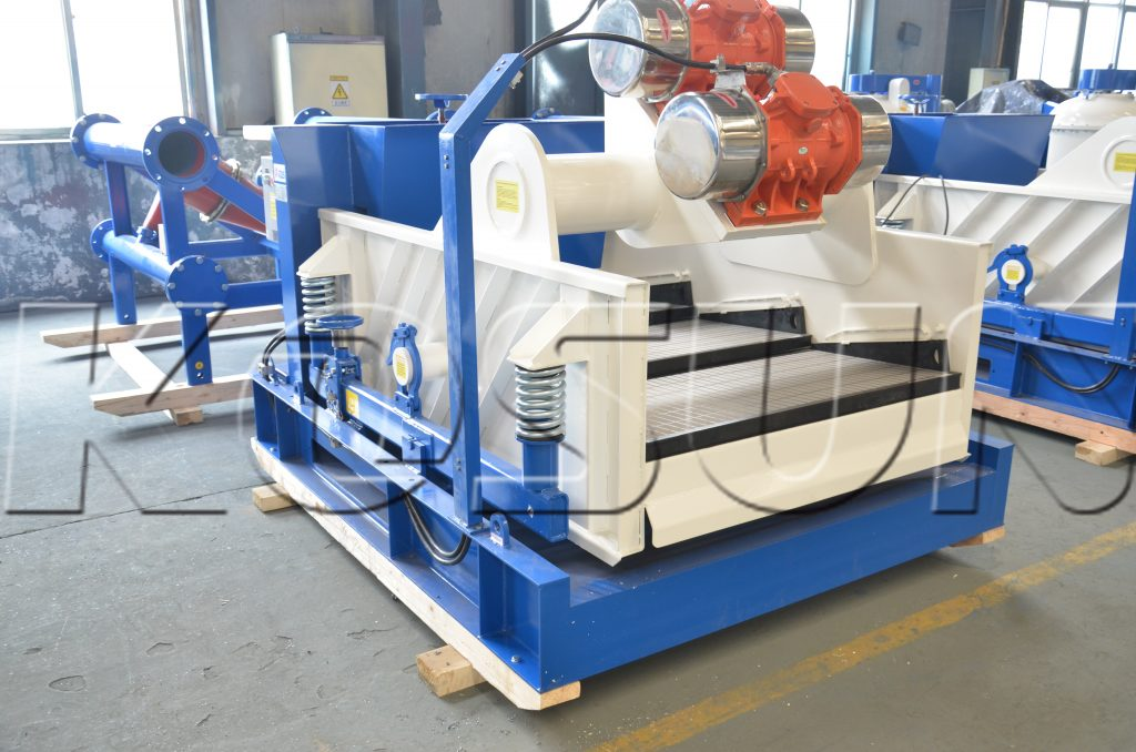
The drilling fluid vibrating screen occupies a unique position in the mud control system. Positioned at the very front of the process, it handles solid-liquid separation earlier, faster, and more economically than any downstream equipment. Its working efficiency effectively sets the processing ceiling for the entire system. Because of this, identifying what drives — or limits — screen performance is essential for any drilling operation. Three factors dominate: vibration mode, amplitude and frequency, and screen mesh characteristics. KOSUN provides high-performance vibrating screens engineered to maximize efficiency across all three dimensions.

Factor One: Vibration Mode

Vibration mode shapes how solids travel across the screen surface. Vibrating screens generally operate in one of three patterns: linear, circular, or elliptical motion. The deciding variable is where the vibrator’s center of gravity sits.

Within the vibrator: The screen produces circular motion.

Above the vibrator: The screen generates elliptical motion, which depends on screen slope to move cuttings — a design that trades processing capacity for conveyance.

Above and slightly forward: The screen delivers linear motion, sustaining a consistent conveying speed.

In practice, linear motion has become the standard for most drilling operations because it balances conveyance and capacity effectively.

Factor Two: Amplitude and Frequency

Amplitude and frequency together control how aggressively the screen processes fluid. Frequency rises and falls with motor speed, and higher frequencies generally improve solid-phase separation. High-frequency vibrating screens, for instance, commonly operate at roughly 2,000 vibrations per minute.

Amplitude describes the vertical travel of the screen, set by vibration mass and eccentricity. Increasing amplitude can strengthen processing performance — but it also raises mechanical stress on the equipment, which can shorten service life. Consequently, operators must weigh separation performance against long-term durability.

Factor Three: Screen Mesh and Material

Screen mesh and material form the final performance layer. Most shale vibrating screens carry 2 to 4 screen layers, with drilling fluid flowing through each in sequence for staged classification.

Choosing the wrong mesh size — or operating with damaged screens — sharply reduces separation efficiency. Faulty installation can also cause premature wear or tearing. For these reasons, correct screen material selection and proper installation are both essential to continuous, reliable operation.

The KOSUN Advantage

KOSUN vibrating screens bring clear strengths to oil drilling applications. Their modular design and high-precision manufacturing ensure smooth, dependable operation. Multiple adjustable vibration modes allow adaptation to different formations and drilling requirements. High-quality motors and shock absorption systems sustain high-frequency screening efficiency while extending equipment life. Finally, high-strength composite screen mesh materials combined with sound structural design significantly boost screen durability and processing efficiency — delivering an economical, all-around solids control solution.

Conclusion

Understanding vibration mode, amplitude and frequency, and screen mesh characteristics gives operators the tools to select and fine-tune their drilling fluid vibrating screen for peak efficiency. The right screen translates into better solids removal, longer equipment life, and reduced drilling costs. KOSUN is committed to providing high-performance vibrating screens and expert support to help customers achieve their operational goals.

Mud Cooling Under Water Scarcity: Solutions for Onshore Drilling

In modern deep-well and geothermal exploration, surface mud cooling represents a critical technical necessity. High bottom-hole temperatures cause circulating fluid to absorb immense thermal energy. Without surface cooling, this cumulative heat triggers severe chemical and mechanical degradation across the drilling asset. Managing this thermal profile is essential for stabilizing fluid chemistry and protecting downhole infrastructure. KOSUN offers advanced mud cooling systems engineered for optimal performance in water-restricted environments.

Onshore Thermal Management: Tailoring Systems to Local Water Access

Onshore equipment selection must align precisely with local utility access and the availability of cooling water. Different water conditions demand different cooling strategies.

  1. Direct Cooling for Water-Abundant Sites

Where water supplies are unrestricted, direct cooling offers an optimized, high-throughput solution. The simple architecture features large-diameter inlet piping to minimize clogging from suspended solids. Operating under standard conditions, systems like the KSNQ-150 utilize a 1.6 MPa design pressure to deliver a stable 20°C to 30°C temperature drop at capacities up to 150 m³/h .

  1. Closed-Circuit Configurations for Water Conservation

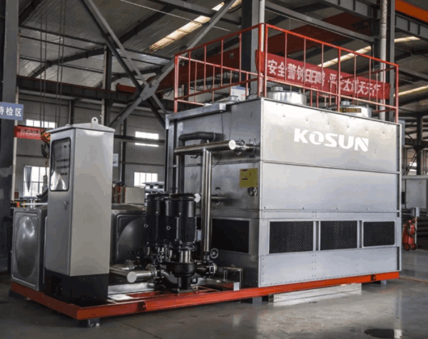
When environmental regulations or supply costs demand strict water conservation, a split-system design is required. This setup pairs a large plate heat exchanger with a small cooling tower. This closed-circuit arrangement isolates the active drilling fluid, minimizing evaporation losses while handling displacements up to 200 m³/h .

  1. Air-Cooled Systems for Arid Environments

In desert regions completely devoid of water, operators must rely on ambient air as the heat sink. This setup combines a heavy-duty plate heat exchanger with high-velocity air coolers. It represents a highly sustainable choice for remote fields, offering zero recurring water consumption after the initial equipment investment.

  1. Chiller-Integrated Solutions for Sub-Ambient Cooling

A critical technical bottleneck arises in hot climates when the required target mud temperature falls below the ambient air temperature. In these water-scarce scenarios, a dedicated chiller unit is introduced into the air-cooler circuit. This hybrid process overcomes ambient thermal limits to provide reliable cooling for high-displacement flows up to 200 m³/h .

Offshore Thermal Management: Overcoming Footprint and Corrosion Limits

Offshore platform deployments introduce unique structural constraints. Space margins are extremely tight, and highly corrosive marine environments rule out standard metallurgy.

  1. Titanium Plate Heat Exchangers Utilizing Seawater

Offshore fluid cooling relies on the platform’s most abundant resource: seawater . To withstand aggressive chloride stress corrosion, the system utilizes specialized titanium plate heat exchangers . Titanium provides excellent thermal conductivity alongside absolute resistance to seawater pitting.

Furthermore, this configuration addresses severe deck space limitations by offering a highly compact footprint . These modules can function as standalone units or be linked in parallel combinations to accommodate higher mud displacement volumes during critical-path drilling phases.

Conclusion

Effective thermal management requires a precise engineering match between environmental limits and mechanical architecture. Whether deploying air-cooled desert skids or compact offshore titanium heat exchangers, stabilizing mud temperature remains the primary means of eliminating high-temperature drilling hazards. KOSUN is committed to providing high-performance mud cooling solutions and expert support to help customers achieve their operational goals.