
Diesel Mud Mixing Skids: Fluid Prep Without the Grid

Diesel driven mud mixing equipment helps HDD contractors prepare drilling fluid at sites where a separate power source is needed. KOSUN’s unit integrates a diesel engine, a centrifugal pump, and a Venturi mixing hopper into a single skid-mounted package — bringing the key mixing and pumping components together for field use.

For horizontal directional drilling crews, that integration matters. Drilling fluid supports the borehole and carries cuttings out of the hole, so proper fluid preparation plays an important role in daily site operations. When power access is uncertain, a self-contained mixing unit removes one variable from the equation.
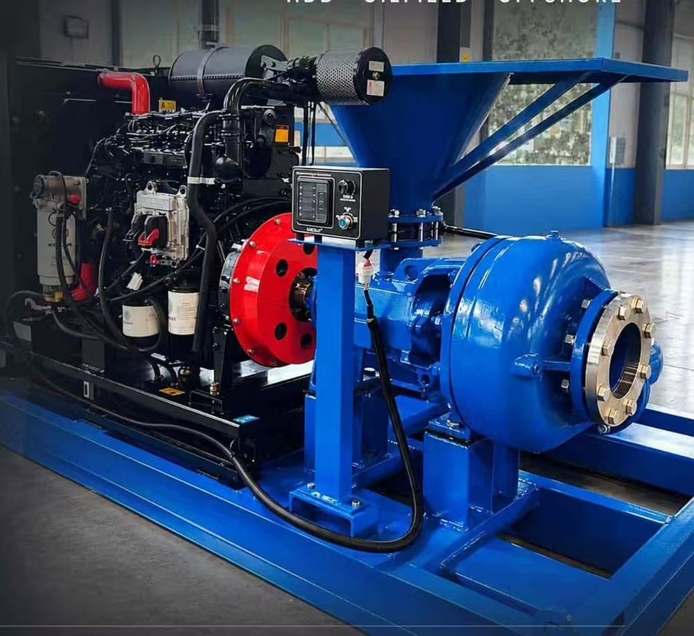
Supporting Drilling Fluid Preparation

During horizontal directional drilling (HDD), drilling fluid performs two essential jobs: it supports the borehole wall and transports cuttings back to the surface. Because the fluid does so much of the work, its preparation deserves attention every day on site.

The diesel engine drives the centrifugal pump , which supplies fluid to the Venturi mixing hopper. Operators then add bentonite and other suitable additives to prepare the drilling fluid. The exact process depends on the fluid recipe and project requirements.

The Venturi design is central to how this works. As fluid passes through the hopper at high velocity, it creates a vacuum that draws in dry additives and disperses them into the fluid stream. This produces a more uniform mixture than simple agitation alone.

Why Consider a Diesel-Driven Unit?

Some drilling sites have limited access to a suitable electrical supply. In these cases, a diesel-driven unit provides an alternative power option for mixing and pumping tasks — one that does not depend on the local grid or on temporary power arrangements.

This is particularly relevant for HDD work, which often takes place where infrastructure is minimal: rural pipeline routes, remote river crossings, or urban sites where temporary power connections are impractical. A diesel-driven unit keeps fluid preparation running regardless of what the site offers.

Moreover, the skid-mounted design groups the main components into one unit. This helps contractors plan equipment placement and arrange the mud handling area more easily, since the mixing system arrives as a single package. A compact footprint also simplifies relocation between job sites.

That said, contractors should still check available space, required flow rate, and site conditions before selecting a configuration.

Match the Equipment to the Project

Every HDD project has its own drilling conditions and fluid needs, and the mixing equipment should follow from those conditions rather than from a generic specification sheet.

Contractors should consider:

  • Planned bore length: longer bores generally require larger fluid volumes and more continuous mixing
  • Soil conditions: sand, gravel, clay, and rock each call for different fluid properties
  • Drilling fluid volume: the total volume in circulation shapes the required mixing capacity
  • Equipment already available on site: the mixing unit should complement existing assets rather than duplicate them

They should also review how the mixing unit will work with mud tanks, pumps, and other parts of the mud system. With these details in mind, contractors can choose a setup that better fits their field operations.

Explore KOSUN Mud Mixing Solutions

KOSUN offers equipment for drilling fluid preparation and related field applications. The diesel-driven mixing skid is one option within a broader range of solids control and mud handling equipment.

Contact the team to discuss your project requirements and find a suitable equipment configuration.

Conclusion

Diesel driven mud mixing equipment gives HDD contractors a practical way to prepare drilling fluid where reliable electrical power is not available. By combining a diesel engine, centrifugal pump, and Venturi mixing hopper on a single skid, KOSUN’s unit simplifies equipment planning while supporting consistent fluid preparation. Matching the unit to your project’s bore length, soil conditions, fluid volume, and existing equipment ensures it contributes to the operation rather than complicating it.
Cavitation in Centrifugal Pumps: Causes, Warning Signs, and Prevention

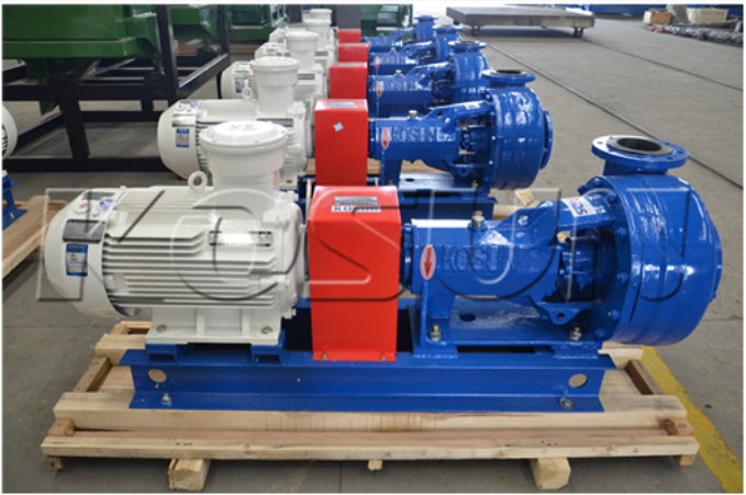
Cavitation ranks among the most destructive conditions a centrifugal pump can face. When local fluid pressure falls below the liquid’s vapor pressure, small vapor bubbles form inside the pump. These bubbles then collapse violently as pressure recovers, sending microscopic shock waves into metal surfaces. Over time, this process erodes impellers, damages casings, and shortens mechanical seal life — outcomes no drilling contractor can afford. Understanding what triggers cavitation and how to stop it is the first step toward protecting your pump investment. KOSUN offers centrifugal pumps engineered for reliable performance in demanding drilling environments.

Understanding Cavitation in Centrifugal Pumps

Before discussing prevention, it helps to know what cavitation looks like in the field. Too often, field teams miss early warning signs, turning a fixable problem into an expensive machine failure.

What Cavitation Looks Like

Cavitation in a centrifugal pump usually produces a rattling or cracking sound — often resembling gravel moving through the case. You may also notice erratic flow rates, fluctuating discharge pressure gauge readings, or visible vibration on the pump body. None of these are normal operating sounds.

How It Progresses

If cavitation pitting on impeller vanes and casing walls goes unaddressed, it worsens. Vibration pushes mechanical seal faces out of alignment, leading to leaks. Bearing loads rise. What begins as noise becomes structural damage that requires replacing the entire pump rather than servicing it.

Why It Matters for Drilling Operations

A centrifugal pump moves slurry between land rigs and offshore platforms, continuously handling rough, heavy fluids. Cavitation compounds the wear these fluids already cause, accelerating degradation far beyond what either problem would produce alone. Even a brief pump outage halts the drilling fluid circuit for mud engineers managing solids control systems.

Root Causes of Cavitation

Cavitation doesn’t appear without warning. It follows predictable patterns tied to fluid conditions, system design, and pump selection. To make the right fix, you need to pinpoint the exact issue in your program.

Insufficient Net Positive Suction Head (NPSH)

The leading cause is usually insufficient available NPSH — when suction-side pressure does not exceed the pump’s required NPSH by a safe margin. This can occur with long suction lines, excessive suction lift, clogged strainers, or high fluid temperatures. Industry standards recommend maintaining at least 3 feet of NPSH above the pump’s rated minimum.

Operating Away from the Best Efficiency Point

Every centrifugal pump has a Best Efficiency Point (BEP) on its performance curve — the flow rate where it operates most efficiently. Running significantly faster or slower than that flow rate alters internal pressure distribution and creates recirculation zones where vapor pockets form. Cavitation becomes a serious risk for pumps forced to operate outside their design conditions for extended periods.

Mechanical and Installation Factors

Worn impellers change internal clearances and reduce hydraulic effectiveness. Air leaks on the suction side, partially closed suction valves, or undersized piping can all restrict flow and lower local pressure. In the field — especially on mobile rigs or frac trucks — vibration can loosen fittings, admitting air and worsening cavitation behavior.

Practical Methods to Prevent Cavitation

Repairing is far more expensive than preventing. Cavitation can be stopped at its source through a structured approach covering system design, operating procedures, and equipment selection.

Optimize the Suction System

Keep suction lines short and straight. Use the largest practical pipe diameter on the suction side. Position the pump as close to the fluid source as possible, and clean suction strainers regularly. These steps raise available NPSH immediately — without modifying the pump itself.

Select the Right Pump for the Application

Off-BEP operation can be avoided when pump volume, head grade, and speed all match system requirements. As long as the centrifugal pump is properly sized for the solids control system’s flow range, it will spend most of its life near its most efficient point, where cavitation risk is lowest. KOSUN centrifugal pumps are built to handle slurry continuously, with open impellers and wide vane profiles that maintain stable fluid flow across a broad operating range.

Implement Routine Monitoring

Regularly checking suction pressure, discharge pressure, and sound levels can catch small problems early. Handheld acoustic monitoring instruments can detect the characteristic cavitation sound at low levels before damage occurs. Maintaining an accurate operating log also helps identify slow performance changes that may signal wear or system drift.

Design and Material Considerations

Hard iron and high chrome metals outperform standard cast iron against the combined attack of abrasive slurry and cavitation-induced pitting. KOSUN centrifugal pumps are available in hard iron , high chrome , aluminum bronze , and stainless steel — giving sourcing teams material options matched to fluid type and wear severity.

An open impeller lowers axial thrust loads, while an impeller retention bolt prevents impeller damage during brief reverse rotation. Wide-vane design improves fluid passage and reduces low-pressure zones where vapor bubbles form. For heavy-duty applications, KOSUN centrifugal pumps feature back vanes on the rotor that prevent solids buildup near the stuffing box and lower internal case pressure, further reducing cavitation likelihood.

Troubleshooting a Suspected Cavitation Event

When noise or performance loss appears, inspect the suction side first — verify valve position, filter condition, and suction line integrity. Then compare the operating point against the pump curve. If the system has changed — flow requirements, longer pipe runs, or different fluid density — adjust NPSH margins before assuming the pump has failed.

Procurement Checklist

When specifying centrifugal pumps, prioritize:

  • Material construction matched to fluid abrasiveness and pH
  • Hydraulic performance curves verifying BEP covers your operating range
  • Seal options and spare seal lead times
  • Spare parts compatibility across pump sizes
  • 24/7 technical support, especially for offshore or remote sites

These requirements lead directly to fewer unexpected shutdowns and lower total cost of ownership.

Conclusion

Cavitation in a centrifugal pump is preventable through correct system design and proper equipment selection. The essentials are suction head margins, operating point accuracy, material durability, and routine monitoring — principles that apply equally on land, offshore, or on mobile rigs. KOSUN manufactures centrifugal pump lines designed for continuous slurry service in demanding oil and gas environments. Choosing a pump built for your specific conditions — backed by responsive technical support and readily available replacement parts — is the most reliable way to keep mud flowing smoothly for the long term.

Vacuum Degasser: Protecting Solids Control Assets and Reducing NPT

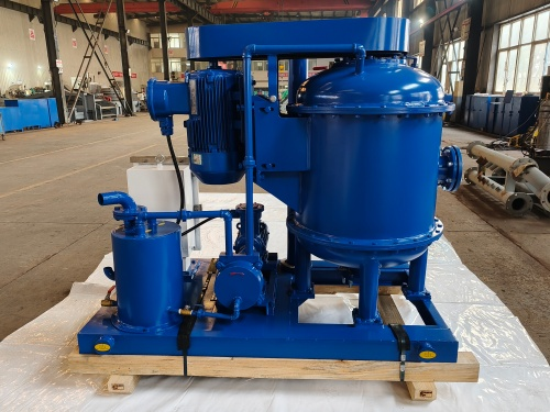
As the global drilling industry pushes for cost reduction and efficiency gains in 2026, minimizing Non-Productive Time (NPT) has become a central objective. Controlling solids content is only part of the equation, eliminating micro-bubbles from drilling fluids is equally critical to protecting expensive solids control assets and trimming maintenance expenditures. Pre-treatment through a vacuum degasser is, in essence, a high-yield investment in asset integrity. KOSUN offers advanced vacuum degassers engineered to protect downstream equipment and extend service life.

Microscopic Cavitation Damage to Precision Metal Surfaces

When gas-cut mud enters centrifugal pumps or high-speed decanter centrifuges, it triggers destructive cavitation. As gas bubbles collapse abruptly in high-pressure zones, the resulting shockwaves repeatedly strike impellers and bearings. Originally smooth metal surfaces become pitted like honeycombs or suffer large-scale spalling, leading directly to the premature scrapping of core components. KOSUN’s vacuum degassers effectively remove entrained gas, preventing cavitation and protecting critical equipment.

Hidden Costs of Volumetric Efficiency Loss and System Energy Consumption

Due to the compressibility of gases, when a mud pump processes gas-entrained fluid, a portion of the power is absorbed by the gas compression process, severely compromising the pump’s volumetric efficiency. This phenomenon also leads to significant pressure fluctuations. Beyond reducing efficiency, the resulting violent vibrations are “silent killers” of high-pressure manifolds and sensors. By degassing, pump pressure fluctuations can be significantly stabilized, protecting consumables such as pistons, valves, and seats, effectively extending their replacement cycles.

Performance Multipliers in Closed-Loop Solids Control Systems

The operational logic of modern solids control systems is interconnected. The presence of gas bubbles artificially inflates the apparent viscosity of the mud, making it thick and difficult to separate. Bubbles act like “glue,” encapsulating fine sand particles and disrupting the stability of the centrifugal field inside hydrocyclones, which compromises the performance of desanders and desilters. As a critical intermediate link, the vacuum degasser ensures that downstream centrifuges achieve precise solid-liquid separation at high speeds by thoroughly eliminating entrained gas.

Strategic Investment Driving OPEX Optimization

The value of a vacuum degasser extends far beyond a single piece of equipment. It creates significant gross margin for drilling contractors by reducing the replacement frequency of expensive spare parts (such as pump fluid end modules and centrifuge drums) and compressing downtime caused by equipment failure. In the capital-intensive world of oilfield services, the vacuum degasser is an essential tool for achieving Equipment Life Cycle Management. KOSUN is committed to providing high-performance vacuum degassers and expert support to help customers achieve their operational and financial goals.

Conclusion

A vacuum degasser is more than just a gas removal device, it is a strategic investment in equipment longevity, operational efficiency, and cost control. By eliminating destructive micro-bubbles, it protects pumps, centrifuges, and downstream equipment from cavitation, wear, and premature failure. For any drilling operation seeking to reduce NPT and optimize OPEX, a high-performance vacuum degasser is an essential component of the solids control system.