Maximizing Shale Shaker Efficiency in High-Volume Drilling Operations

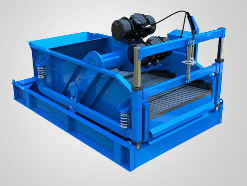
In high-volume drilling, maximizing shale shaker efficiency is critical for maintaining productivity and controlling costs. Shale shakers are the primary equipment used to separate drill cuttings from drilling fluid. When optimized properly, they improve solids control, reduce waste, and support environmental compliance. This article outlines key strategies, including adjustments to angle and flow rate, preventive maintenance, and modern monitoring systems. KOSUN offers high-performance shale shakers engineered for reliable operation in demanding drilling environments.
Optimal Shaker Angle and Flow Rate Adjustments

Efficient performance depends heavily on shaker angle and flow rate, which directly affect separation quality and fluid recovery.

Fine-Tuning Shaker Angle

Shaker angle strongly influences separation behavior. A steeper angle speeds up fluid drainage, while a shallower angle increases retention time for better solids removal. The right balance depends on:

  • Drilling fluid properties
  • Solids concentration and type
  • Processing capacity requirements
  • Screen mesh size and configuration

Many modern shale shakers allow on-the-fly angle adjustments, enabling operators to respond quickly to changing drilling conditions.

Optimizing Flow Rate

Flow rate must be controlled to avoid screen overload or fluid bypass. Proper optimization considers:

  • Screen capacity and design
  • Fluid viscosity and density
  • Solids loading and particle size
  • Required throughput

Flow control systems and monitoring tools help maintain stable, efficient performance throughout operations.

Preventive Maintenance Strategies

A strong maintenance program is essential for continuous shale shaker operation and reduced downtime.

Maintenance Scheduling
  • Key maintenance practices include:
  • Regular component inspections
  • Timely replacement of worn parts
  • Lubrication of moving systems
  • Screen cleaning and unclogging
Sensor calibration

A proactive approach reduces unexpected failures and keeps performance consistent.

  • Screen Selection and Replacement
  • Shaker screens are central to separation efficiency. Important factors include:
  • Mesh size and screen type
  • Compatibility with drilling fluid
  • Solids load conditions
  • Wear patterns and lifespan

Regular inspection helps identify wear or blinding early. High-quality options like PTS (Pre-Tensioned Screens) can extend service life and improve efficiency.

Advanced Monitoring Systems

Real-time monitoring significantly improves operational control and efficiency.

Sensor-Based Performance Tracking

Modern systems use sensors to track key indicators:

  • Vibration sensors for motion balance
  • Flow sensors for distribution accuracy
  • Pressure sensors for screen loading
  • Temperature sensors for fluid and equipment health
  • These inputs help operators make immediate adjustments.
Predictive Maintenance

Machine learning-based systems can analyze sensor data to:

  • Detect early performance degradation
  • Predict maintenance needs
  • Optimize service schedules
  • Support proactive decision-making
  • This reduces downtime and improves overall equipment reliability.
Conclusion

Maximizing shale shaker efficiency requires optimizing operational settings, maintaining equipment proactively, and using real-time monitoring tools. By adjusting angles and flow rates, implementing structured maintenance, and leveraging predictive systems, operators can improve solids control, reduce downtime, and enhance drilling performance.

As drilling demands increase, adopting advanced shale shaker practices is essential for maintaining efficiency, cost control, and environmental compliance. KOSUN is committed to providing high-performance shale shakers and expert support to help customers achieve their operational goals
Mud Gas Separator: Essential Well Control Equipment for Safe Drilling

In oil and gas drilling operations, managing gas invasion is a critical safety concern. A mud gas separator — commonly referred to as a poor boy degasser — is a vital component of well control systems, designed to separate and safely discharge gas from drilling fluids. KOSUN provides high-performance mud gas separators engineered for reliable gas handling in the most demanding drilling environments.

Understanding the Mud Gas Separator

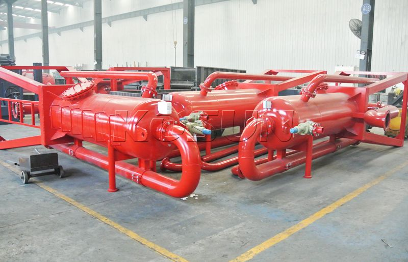
A mud gas separator is a specialized vessel used to remove free gas that enters the drilling mud during a kick or when formation pressure exceeds hydrostatic pressure. If left unchecked, gas-contaminated mud loses density and can lead to dangerous well control situations, including blowouts.

The separator operates by directing gas-cut mud through internal baffle plates, which reduce fluid velocity and allow gas bubbles to rise and escape. The liberated gas is then routed through a vent line, typically to a flare system for safe combustion.

Operating Principle of a Mud Gas Separator

When formation gas enters the wellbore, the mud gas separator performs the following functions:

  • Accepts gas-laden drilling fluid from the well
  • Directs flow over internal baffles to slow movement
  • Allows gas to separate from the liquid phase
  • Vents gas to a safe location or flare system
  • Returns cleaned mud to the circulation system

This sequence ensures that well control is maintained and hazardous pressure buildup is avoided.

Where Mud Gas Separators Are Used

Mud gas separators are essential in a variety of drilling scenarios, including:

  • Well control during kicks and pressure surges
  • Blowout prevention systems
  • High-risk formations prone to gas influx
  • Operations involving toxic gases like hydrogen sulfide (H₂S)
  • Situations with incorrect mud weight leading to gas entry

The KOSUN mud gas separator is specifically designed to handle both free and hazardous gases, making it a trusted solution in challenging drilling conditions.

Key Features and Advantages

Modern mud gas separators offer a range of benefits that enhance safety and performance:

  1. High-Efficiency Gas Removal – Effectively extracts large gas volumes from drilling mud, preserving fluid properties and ensuring safe operations.
  2. Controlled Gas Disposal – Gas is directed to a remote flare system, where it is safely burned, reducing risk to personnel and equipment.
  3. Robust and Corrosion-Resistant Construction – Manufactured from high-grade materials with protective coatings to withstand harsh drilling environments.
  4. Improved Well Control – Maintains pressure balance and prevents kicks and blowouts by ensuring gas is removed before mud returns to the wellbore.
Why Mud Gas Separators Are Indispensable

Mud gas separators are a critical part of any well control strategy, offering:

  • Enhanced safety for rig personnel
  • Protection against hazardous gas exposure
  • Reduced environmental impact
  • Improved drilling efficiency
  • Minimized downtime from gas-related problems

Through efficient gas separation and venting, mud gas separators play a key role in maintaining safe and productive drilling operations.

Conclusion

A mud gas separator is more than just a piece of equipment — it is a safeguard against well control incidents and a cornerstone of drilling safety. By effectively removing gas from drilling fluid, it protects people, equipment, and the environment while supporting efficient operations. KOSUN is dedicated to providing reliable mud gas separators and expert support to help customers maintain the highest standards of safety and performance.


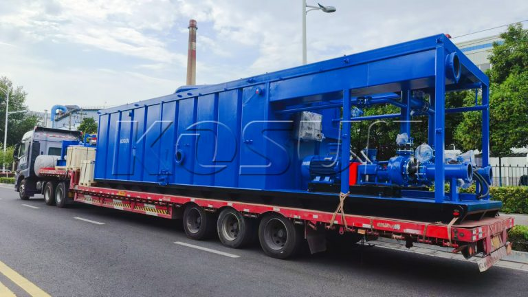
Mud Tank: Essential Component for Efficient Drilling Operations

In the field of drilling operations, efficiency, accuracy, and safety are of utmost importance. The mud tank is one of the key components to ensure the smooth operation of the drilling platform. In this paper, we discuss the significance, function, and characteristics of oil rig mud tanks and reveal the importance of mud tanks for drilling rigs in the oil and gas industry. KOSUN offers high-performance mud tanks engineered for reliable drilling fluid management in demanding environments.

Understanding the Mud Tank System

Mud tanks are specialized containers for the storage and circulation of drilling fluids (also known as drilling mud) during drilling operations. These tanks are designed to withstand the rigors of the drilling site and facilitate the management of drilling fluids throughout the drilling process.

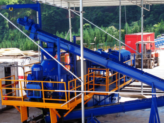
The drilling mud tank is the main storage container for drilling fluids, which can hold the large amount of mud required for drilling operations. It also helps in the mixing and blending of drilling fluids to ensure the uniformity and consistency of mud composition. Mud tanks contain mechanisms for separating solids, such as linear motion shale shakers and decanter centrifuges , to maintain the quality and performance of drilling mud. In addition, some advanced mud tank systems include heating and cooling elements to regulate the temperature of the drilling fluid, optimize its performance, and improve drilling efficiency.

Internal Structure of a Drilling Mud Tank

A drilling mud tank is composed of a tank body, mixing device, discharge port, and feed port.

  1. Tank Body

The body of the mud tank is a sealed container, usually made of welded steel plates. The tank has different shapes such as round, oval, or square, and the size also varies according to the specific use needs. The inner wall of the tank is generally treated with anti-corrosion to prevent the corrosion of the mud on the tank.

  1. Mixing Device

A mixing device is provided inside the mud tank for mixing mud to keep it in a uniform mixing state. The stirring device is usually composed of a motor, a reducer, and a stirrer. The motor transmits power through the reducer to the agitator, which rotates the mud to keep the solids suspended and prevent them from settling at the bottom of the tank.

  1. Discharge and Feed Ports

The mud tank is provided with a discharge port and a feed port for the discharge and entry of mud. The discharge port is usually located at the bottom of the tank and drains the mud through a pipe to the next treatment unit. The feed port is usually located at the top of the tank, and the fresh mud is injected into the tank through the pipe. The location and size of the discharge and feed ports are determined according to the specific design requirements in order to achieve effective mud flow and handling.

We usually add a sand pump beside the tank to provide power to transport mud, and sometimes we have a jet mud mixer to mix the mud.

Conclusion

In the dynamic world of drilling operations, mud tanks are an indispensable asset, providing the necessary infrastructure to effectively manage drilling fluids. From storage and mixing to separation and temperature control, drilling rig mud tanks play a multifaceted role in ensuring the success and safety of drilling operations. With the development of drilling technology, the importance of well-designed and reliable solids control equipment has increased, and it is the backbone of the oil and gas industry as it seeks energy exploration and production. KOSUN is committed to providing high-performance mud tanks and expert support to help customers achieve their operational goals.

Cuttings Dryer: Working Principle and Core Functions for Drilling Waste Management

In modern petroleum drilling engineering, as environmental regulations become increasingly stringent, the effective treatment of oily drill cuttings has become a focal point of the industry. As the core equipment of the Drilling Waste Management System, the cuttings dryer has become the key to achieving mud recovery and waste reduction through its superior solid-liquid separation performance. KOSUN offers advanced cuttings dryers engineered for high-efficiency solids control in demanding drilling environments.

Definition and Application Scenarios of the Cuttings Dryer

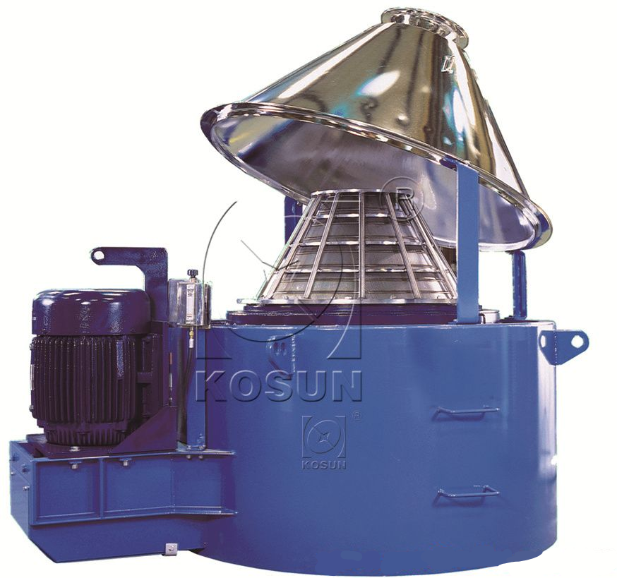
A cuttings dryer (also commonly referred to as a vertical dryer or drill cuttings dryer) is primarily used to treat cuttings generated during drilling processes using Oil-Based Mud (OBM) or Synthetic-Based Mud (SBM). Its core objective is to strip and recover the liquid adhering to the surface of the cuttings using the immense centrifugal force generated by high-speed rotation. This process achieves solid-liquid separation, resulting in drier solids and a significantly reduced oil content on the waste. KOSUN’s cuttings dryers are designed for maximum fluid recovery and minimal waste volume.

Detailed Working Principle of the Cuttings Dryer

Feeding and Acceleration Phase

Oily drill cuttings are fed into the top inlet of the cuttings dryer via conveying equipment (such as a Screw Conveyor ). Upon entering the equipment, the cuttings drop into the center of the high-speed rotating basket (screen).

High G-Force Centrifugal Separation Phase

The rotor (containing the screen basket) rotates at high speeds, generating a centrifugal force (G-force) typically ranging from 300G to 900G . Under this intense force, the oil-based liquid adhering to the solid surfaces passes through the screen gaps and enters the liquid collection tank, while solid particles larger than the screen gaps are retained on the inner side of the screen.

Mechanical Scraping and Assisted Discharge Phase

To prevent solids from accumulating and clogging the inner walls of the screen, the cuttings dryer is designed with internal rotating flights (scrapers). There is a slight speed differential between the scrapers and the screen basket. This controlled differential operation scrapes the dried solids off the screen, allowing them to move toward the discharge outlet at the bottom of the equipment under the influence of gravity.

Liquid Recovery and Purification Phase

The expelled liquid phase (mud containing a small amount of fine particles) is discharged through the liquid outlet. Typically, this recovered liquid is sent to a downstream Decanter Centrifuge for further purification. Once ultra-fine particles are removed, the liquid is finally reintroduced into the active mud system for reuse.

Key Technical Parameters Affecting Cuttings Dryer Efficiency

To achieve optimal treatment results under the latest environmental standards, the following parameters are critical:

  • Screen Gap: Typically selected based on the geological formation and lithology.
  • Centrifugal Force: Higher rotational speeds yield greater centrifugal force and better dehydration; however, this places higher demands on the equipment’s dynamic balance and wear resistance.
  • Scraper Wear Resistance: Since drill cuttings are highly abrasive, high-performance cuttings dryer scrapers are usually reinforced with tungsten carbide or other hard alloys to extend their service life.

KOSUN’s cuttings dryers are engineered with durable materials and precision components for long-term reliability in abrasive drilling environments.

Conclusion

Through efficient physical separation, the cuttings dryer not only solves environmental discharge challenges in oilfield operations but also saves drilling contractors significant material costs through high-ratio mud recovery. KOSUN is committed to providing high-performance cuttings dryers and expert support to help customers achieve their operational and environmental goals.