

The screw conveyor optimizes drilling waste processing by using high torque and an enclosed trough to transport high-viscosity cuttings cleanly and bridge the gap between core solids control assets and zero-discharge networks. Managing heavy, high-density solids remains a major challenge. Raw cuttings carry substantial base fluid, reducing flowability and increasing abrasiveness. Transport spillages contaminate the jobsite directly, while inconsistent feeding causes downstream equipment to suffer from unplanned downtime

Process Integration and Workflows of the Screw Conveyor
The screw conveyor does not operate as an isolated unit within the treatment plant. Instead, the conveyor acts as a structural backbone that links front-end screening equipment with back-end deep drying modules. The standardized real-time process involves four key operational stages:
- Primary Separation and Solids Collection: Raw drilling fluid returning from the wellbore flows across primary and secondary separation equipment, including the drilling shale shaker, desanders, and desilters. These assets mechanically intercept and remove coarse cuttings and sticky mud aggregates, dropping them directly into the feed hopper of the conveyor.
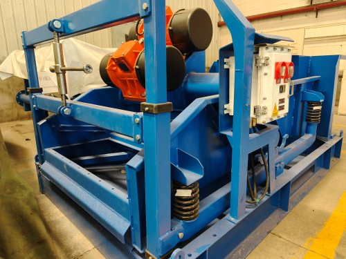
- Enclosed Axial Displacement and Regulation: The machine uses high-strength flights welded onto a central shaft to push wet, high-water-content cuttings uniformly along a U-shaped trough. Operators can deploy these units in horizontal or inclined configurations. Additionally, the variable speed drive allows technicians to adjust fluid velocity in real time, preventing material bridging or plugging at the inlet.
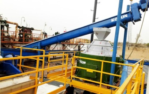
- Secondary Dewatering Feed Stage: The conveyor systematically lifts and delivers the high-solids waste to downstream zero-discharge treatment equipment. This equipment includes the vertical cutting dryer and high-speed decanter centrifuges.
- Final Separation and Sealed Discharge: The downstream drying equipment uses high centrifugal forces to perform final dewatering. Reclaimed base fluids flow back into the active circulation tanks. Concurrently, an inclined secondary screw conveyor accepts the dry cakes, transferring them to designated zones for enclosed stacking and volume-reduced transport.
Modular Engineering and Heavy-Duty Safety Design
Geological formations and rig layouts introduce extreme spatial variations and material diversity. To address these persistent jobsite bottlenecks, KOSUN incorporates modular structures and heavy-duty wear protection into its screw conveyor designs:
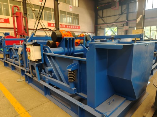
- Flexible Modular Architecture: The conveyor uses a multi-sectional assembly method based on standard 12-foot (3.66-meter) sections. This modular configuration allows engineers to customize the total length to fit tight offshore decks or restricted land jobsites, maximizing spatial adaptability.
- Abrasive-Resistant Metallurgy: To counter the aggressive wear of oil-based mud cuttings, the flighting features specialized corrosion-resistant and wear-resistant alloys. Combined with a compact drivetrain that delivers high torque capacity, this advanced manufacturing process ensures low noise levels, zero oil leakage, and high mechanical uptime.
- Essential Personnel Protection: A ruggedized structural base frame supports and protects the entire conveyor assembly. Furthermore, a standardized grid guard covers the U-shaped trough completely. This mechanical barrier blocks foreign objects from falling into the trough and breaking the shaft, while safeguarding ground crews during operation.
Conclusion
Modern environmental regulations transform the role of the screw conveyor from a simple material handling tool into a core control unit for closed-loop fluid management. Ultimately, implementing this dependable transport technology helps international total contractors lower long-term operational expenditures while satisfying strict international discharge standards.
 System Integration and Process Workflows